 Image 1 of 4
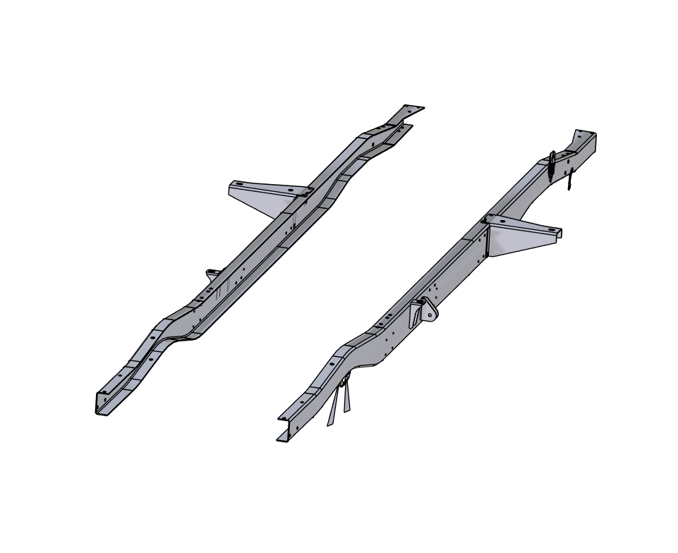 Image 2 of 4
 Image 3 of 4
 Image 4 of 4


Contributor: Patrick Sukraw
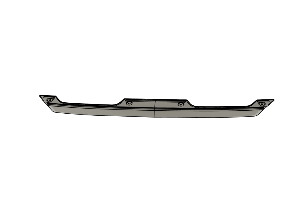
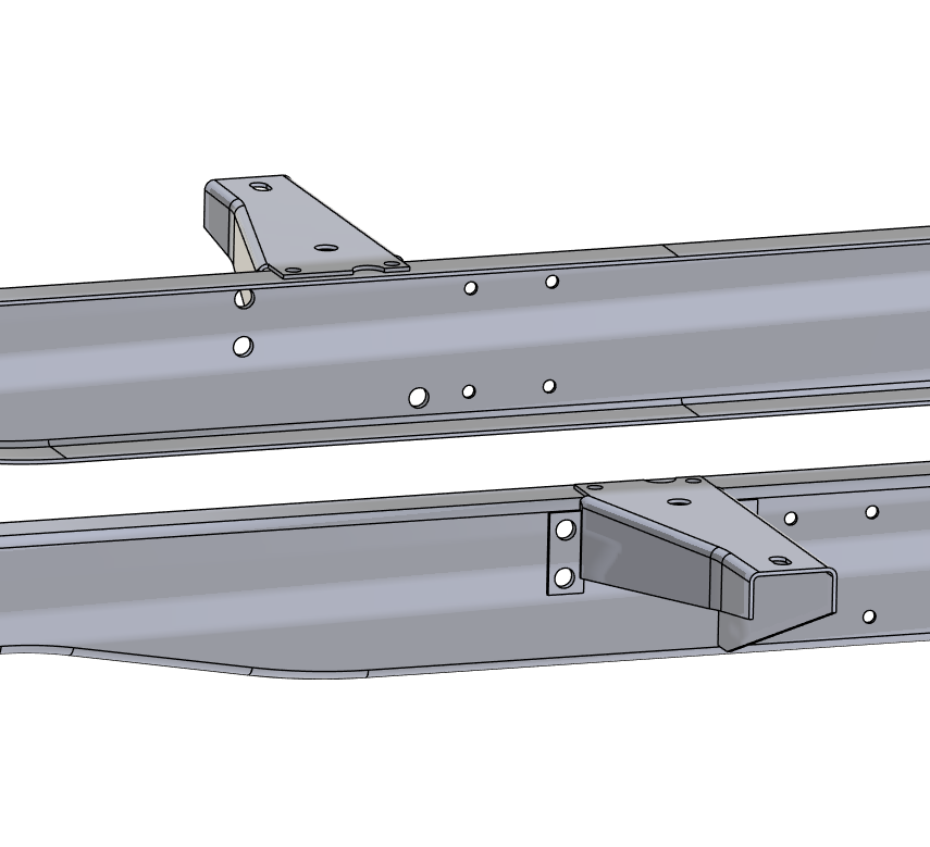
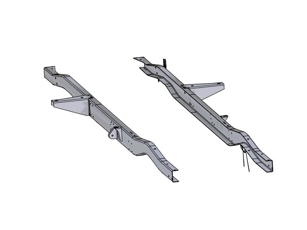
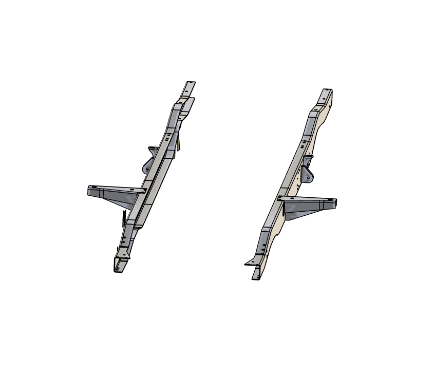
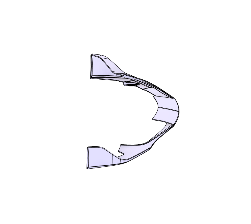
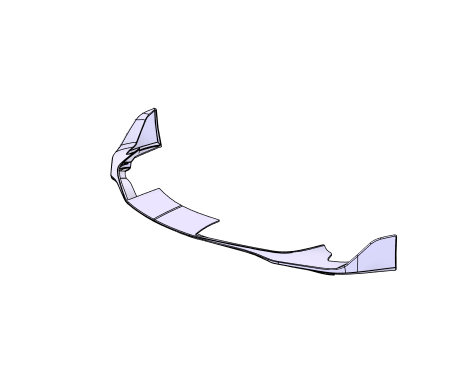
Basic CAD model of a 1953-1956 Ford F-100 Short-Bed (SB) frame, supplied in Parasolid (.x_t / .x_b) format for use in CAD and engineering workflows.
This model includes frame rails and body mount locations only. It is not a complete chassis CAD and does not include suspension components, crossmembers, brackets, drivetrain mounts, or hardware details.
Intended use cases include:
Body-to-frame alignment and positioning
Early-stage chassis layout and packaging studies
Reference geometry for custom frame or suspension development
Digital mockups and concept-level design work
The data provides a simplified representation of the core structural layout, suitable for reference and planning purposes. It is not production-ready and should not be used directly for manufacturing. Dimensions, tolerances, and regulatory considerations are not included.
This model is best suited for builders, designers, and engineers who need a clean, lightweight CAD reference of the 1953–1956 F-100 frame geometry rather than a fully detailed chassis assembly.
Disclaimer:
We encourage you to download the sample file to assess scan format, output quality, and how it performs in your preferred software. Different packages may interpret scan data differently, so verifying compatibility with your workflow is essential.
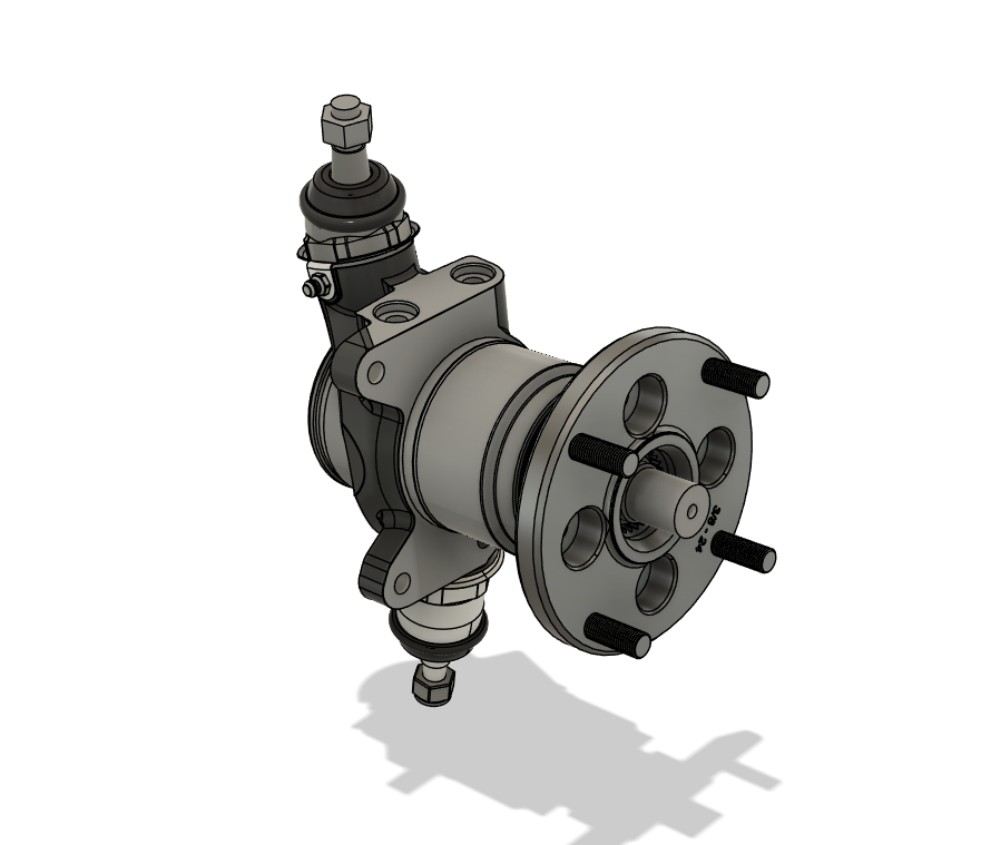
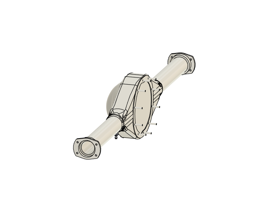
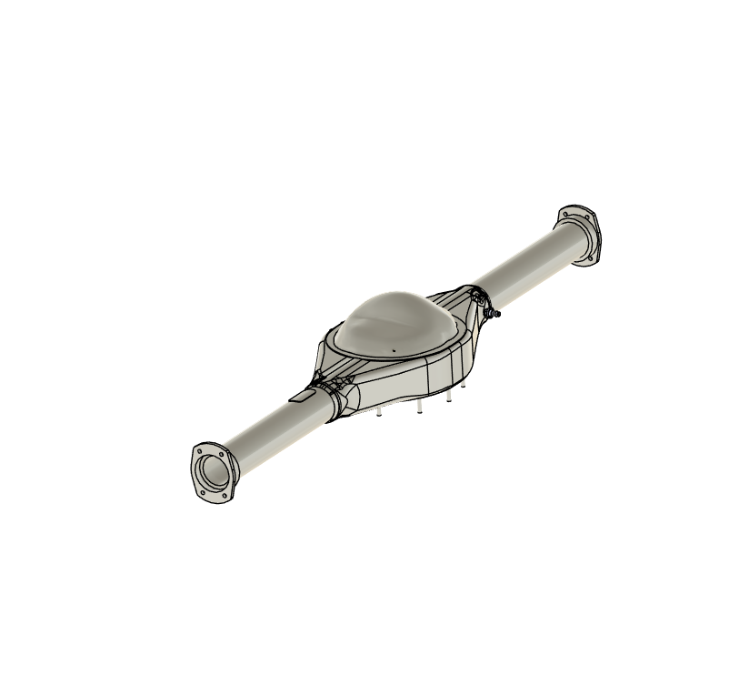
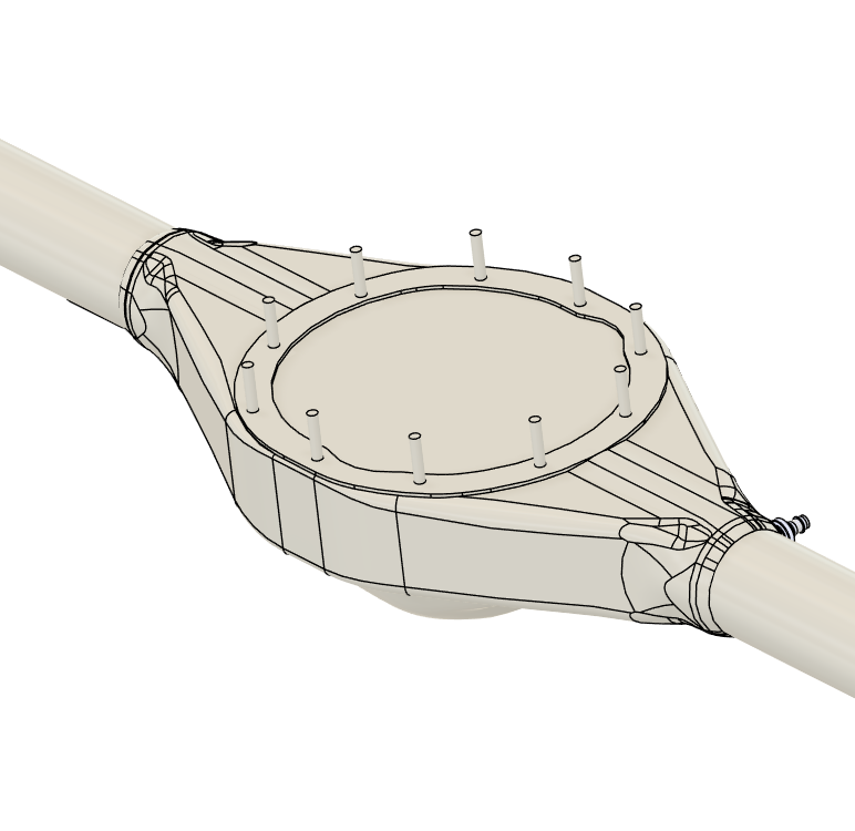
Please refer to the provided part images to evaluate file quality and representation.
While every effort is made during scanning to ensure accuracy, we advise verifying critical dimensions against the physical part if your application requires tight tolerances or precise referencing.
Reviewing both the sample file and images will help ensure the scan meets your requirements before purchase.
Contributor: Patrick Sukraw
Basic CAD model of a 1953-1956 Ford F-100 Short-Bed (SB) frame, supplied in Parasolid (.x_t / .x_b) format for use in CAD and engineering workflows.
This model includes frame rails and body mount locations only. It is not a complete chassis CAD and does not include suspension components, crossmembers, brackets, drivetrain mounts, or hardware details.
Intended use cases include:
Body-to-frame alignment and positioning
Early-stage chassis layout and packaging studies
Reference geometry for custom frame or suspension development
Digital mockups and concept-level design work
The data provides a simplified representation of the core structural layout, suitable for reference and planning purposes. It is not production-ready and should not be used directly for manufacturing. Dimensions, tolerances, and regulatory considerations are not included.
This model is best suited for builders, designers, and engineers who need a clean, lightweight CAD reference of the 1953–1956 F-100 frame geometry rather than a fully detailed chassis assembly.
Disclaimer:
We encourage you to download the sample file to assess scan format, output quality, and how it performs in your preferred software. Different packages may interpret scan data differently, so verifying compatibility with your workflow is essential.
Please refer to the provided part images to evaluate file quality and representation.
While every effort is made during scanning to ensure accuracy, we advise verifying critical dimensions against the physical part if your application requires tight tolerances or precise referencing.
Reviewing both the sample file and images will help ensure the scan meets your requirements before purchase.
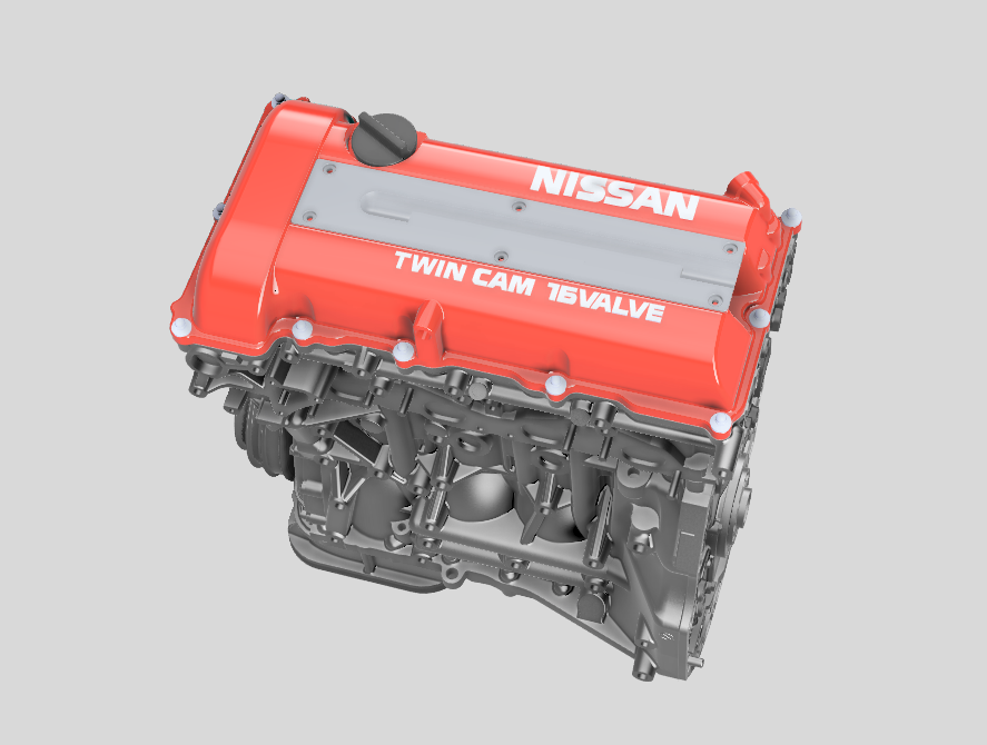
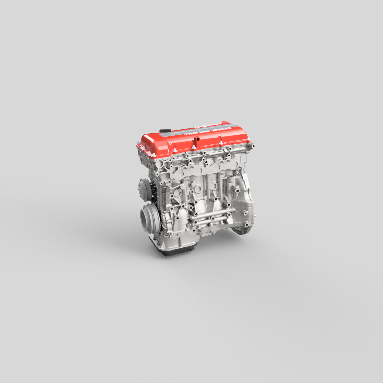
![Nissan SR20 Engine CAD - 3D Model (STEP) [Item: SBU]](https://images.squarespace-cdn.com/content/v1/5aaee99b96e76f27dc94b28a/30c505f9-c229-4b77-85d4-6e5272621260/Fusion360_MEBoil31pV.png)
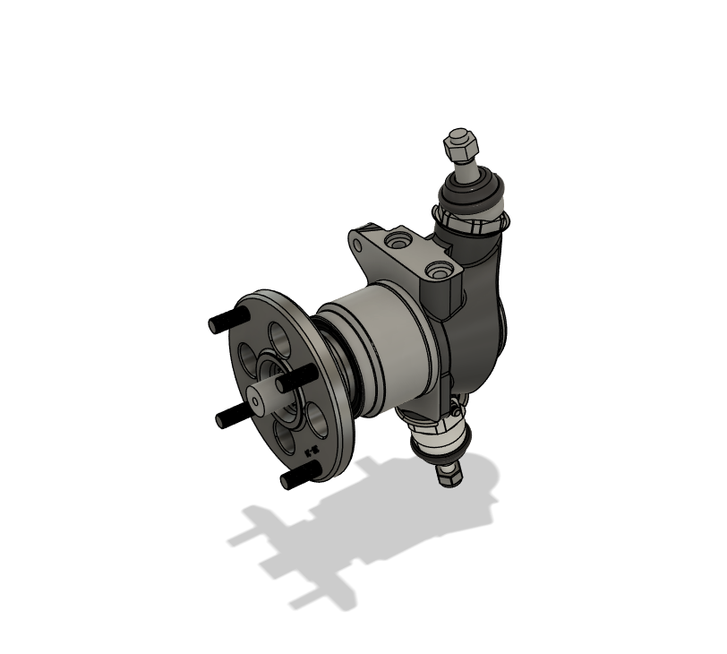
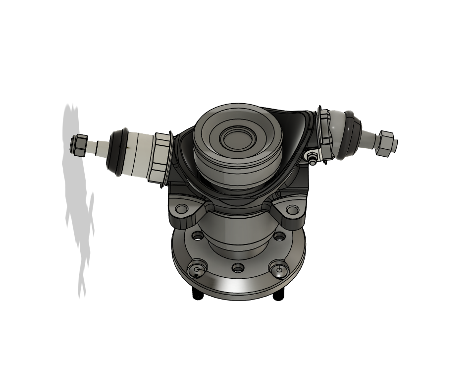
![Mini Sport Swivel Hub - CAD Model (STEP) [Item: LHO]](https://images.squarespace-cdn.com/content/v1/5aaee99b96e76f27dc94b28a/abe02636-8807-4321-ac09-64c7bf5e3a41/Fusion360_YR98TxYYnX.png)

![CURRIE Centurion Notchback Housing - CAD (.X_T) [Item: PSU]](https://images.squarespace-cdn.com/content/v1/5aaee99b96e76f27dc94b28a/163eb28f-36f9-4706-b748-4215964301db/Fusion360_B3jlTSpQ4v.png)

![2020 Toyota Supra Front Lip Model - CAD (.step) [Item: AC3]](https://images.squarespace-cdn.com/content/v1/5aaee99b96e76f27dc94b28a/e7a20cd6-5cd2-45f6-a4a7-a5b10237a77b/Fusion360_nhCcVOmqB7.png)

![2020 Mustang Shelby GT500 Rear Trunk Lip Model - CAD (.step) [Item: AC3]](https://images.squarespace-cdn.com/content/v1/5aaee99b96e76f27dc94b28a/e7a67ae0-d803-47c9-806d-fd6e6df7381b/Fusion360_ACOlsifp0P.png)