Collaborator: Matthew Hillocks
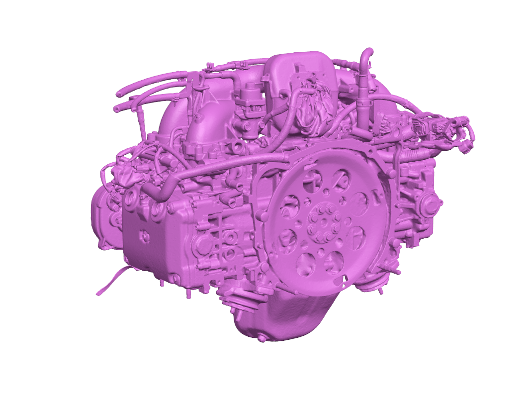
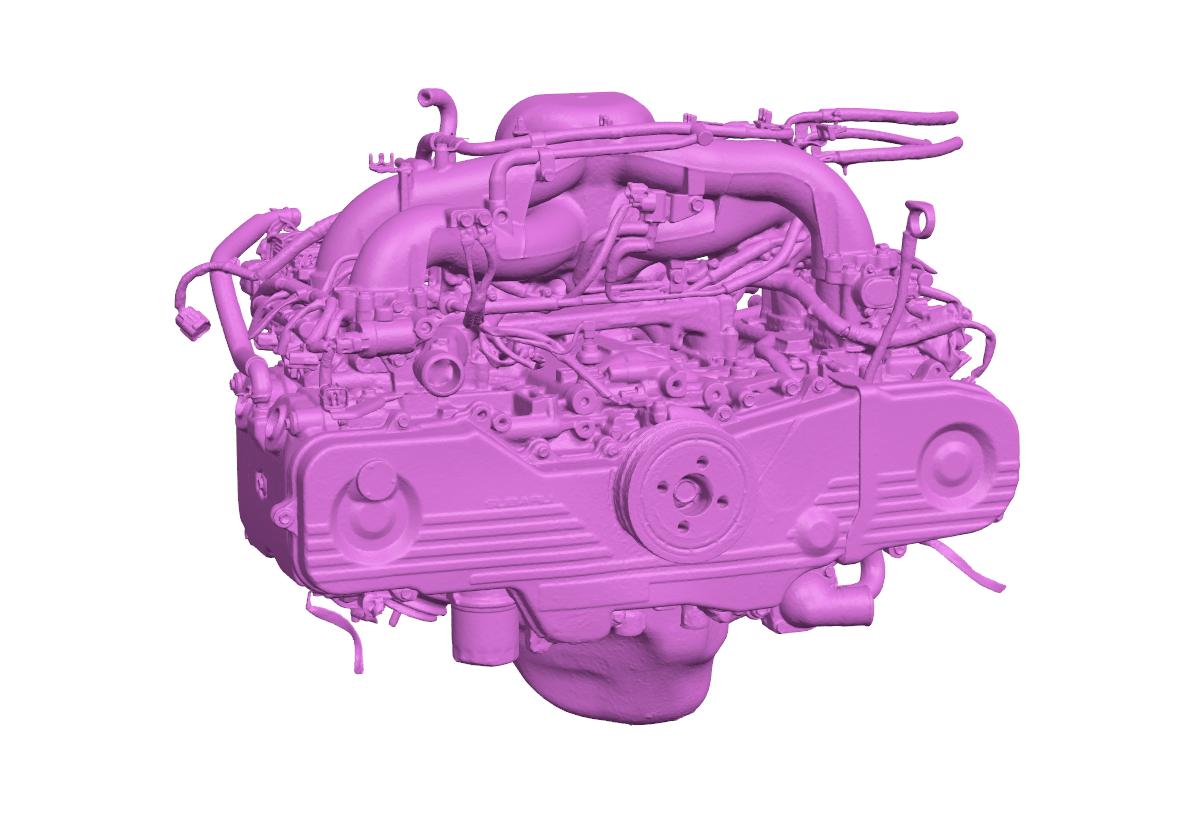
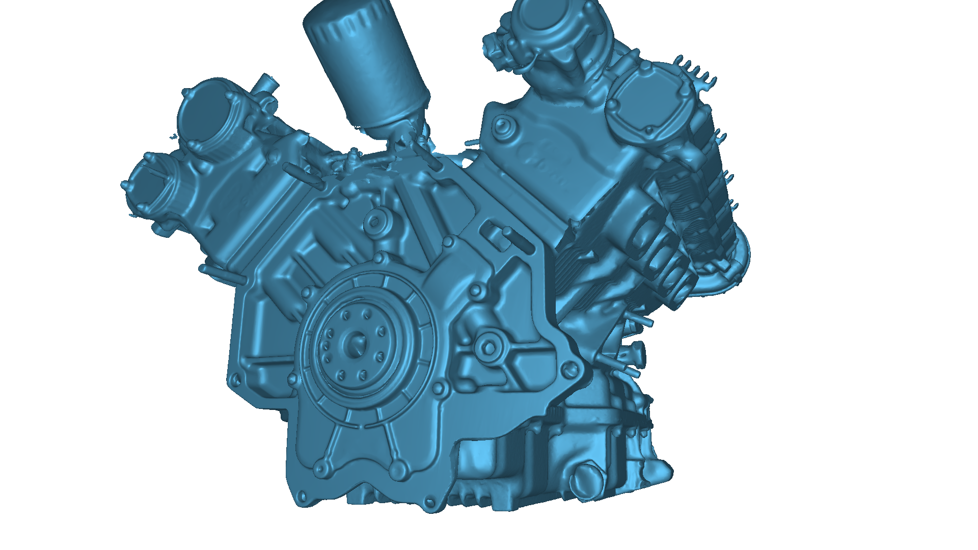
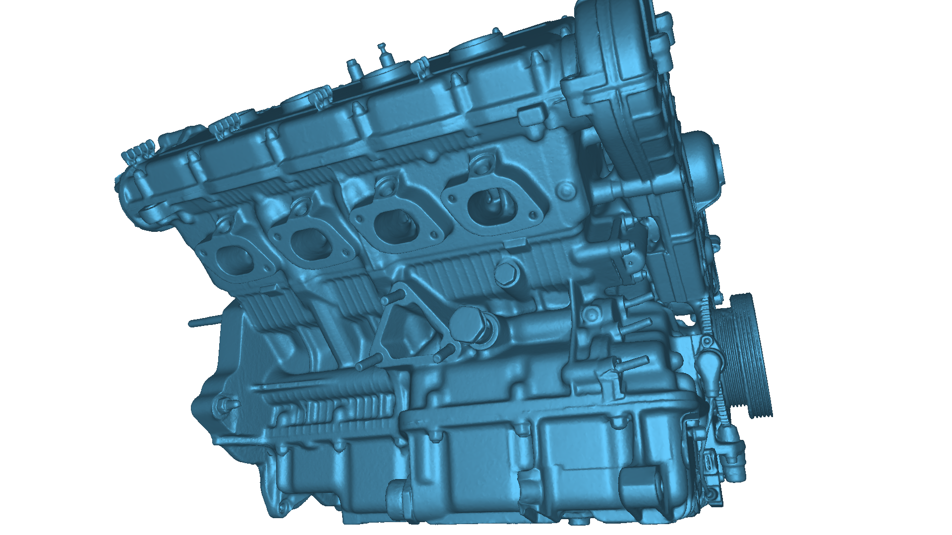
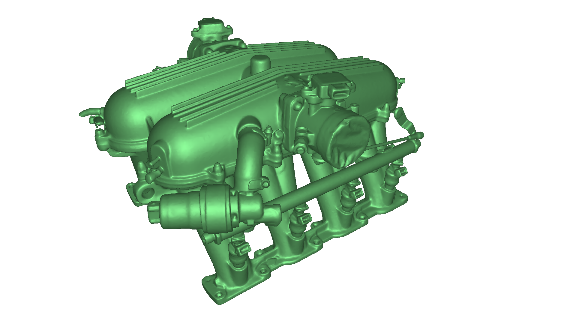
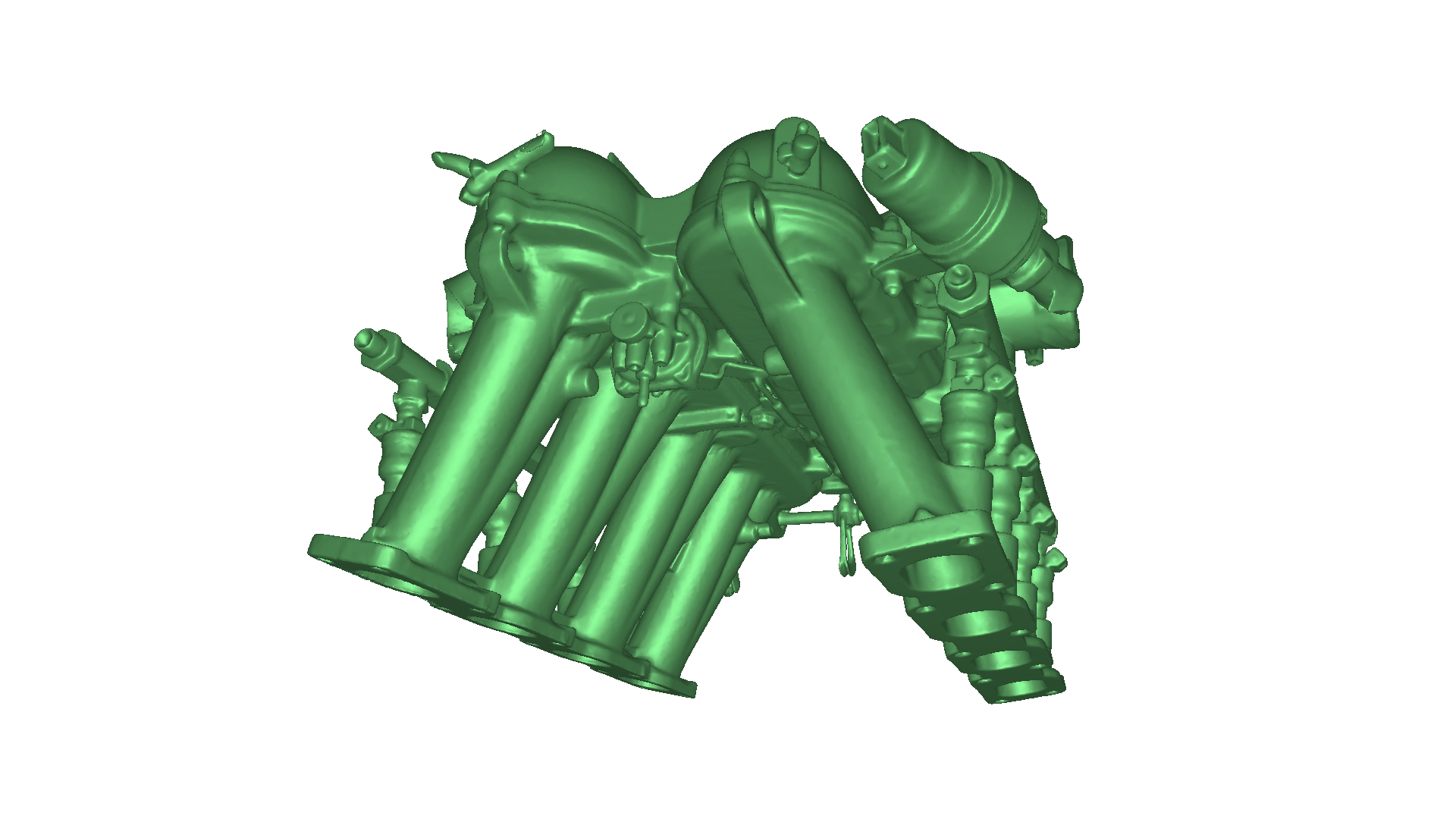
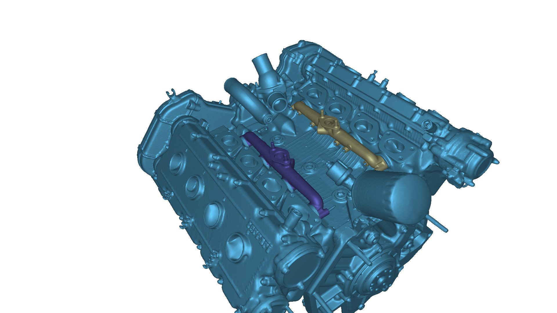
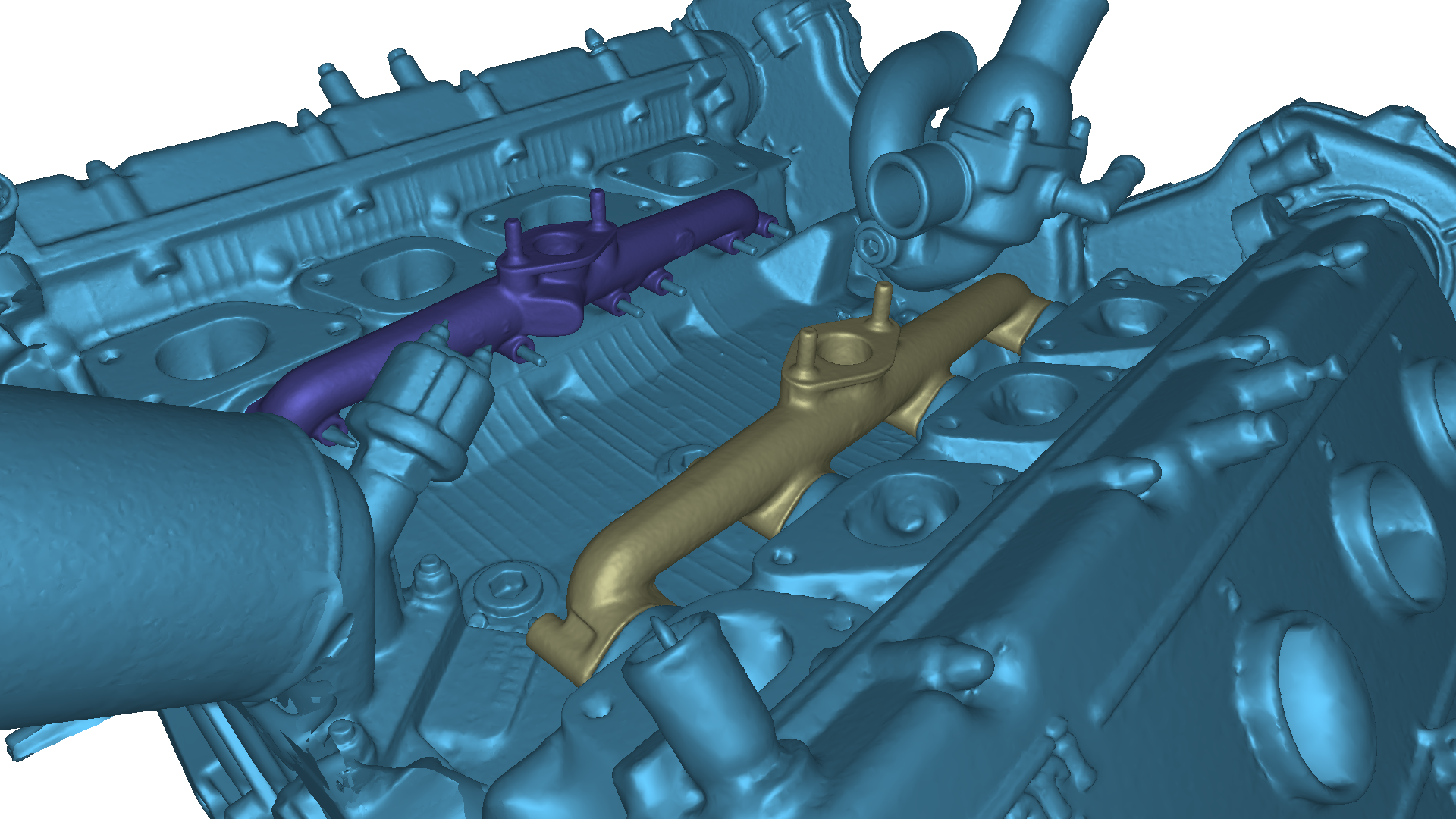
This listing provides a high-resolution 3D scan of a Ford Windsor 351 engine block, capturing the key external casting geometry and major mounting interfaces used across a wide range of Ford V8 applications. The scan is well suited for engine development, fitment validation, reverse engineering, and CAD-based engineering workflows.
The Ford Windsor 351 (351W) is a cast iron 90-degree V8 engine block that has become one of Ford's most popular small-block platforms. Its widespread use in passenger cars, trucks, motorsport, and aftermarket performance applications makes it a valuable reference for restoration, fabrication, and custom engine projects.
Scan Compatibility
Compatible with Ford Windsor 351 engine applications (please verify your specific block variant and configuration for your intended use).
Common Applications
Engine bay layout and packaging
Engine mount and accessory bracket development
Custom fabrication and engine swap projects
Reverse engineering for replacement or performance parts
CAD reference and engineering workflows
3D visualization and simulation
File Suitability
Ideal for CAD reference, packaging studies, reverse engineering, and vehicle engineering workflows.
Important Notes
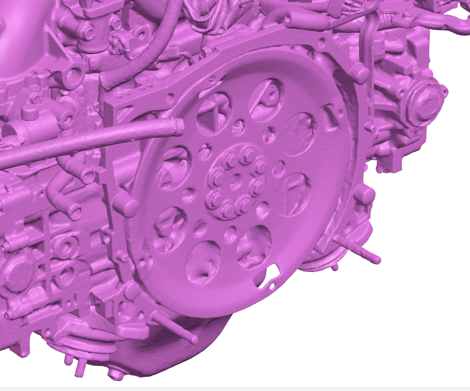
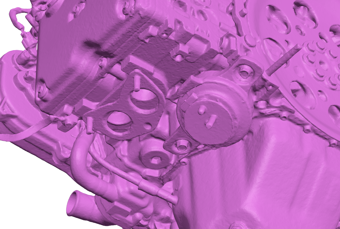
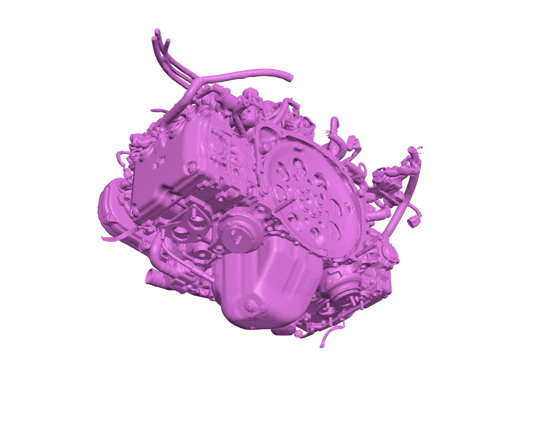
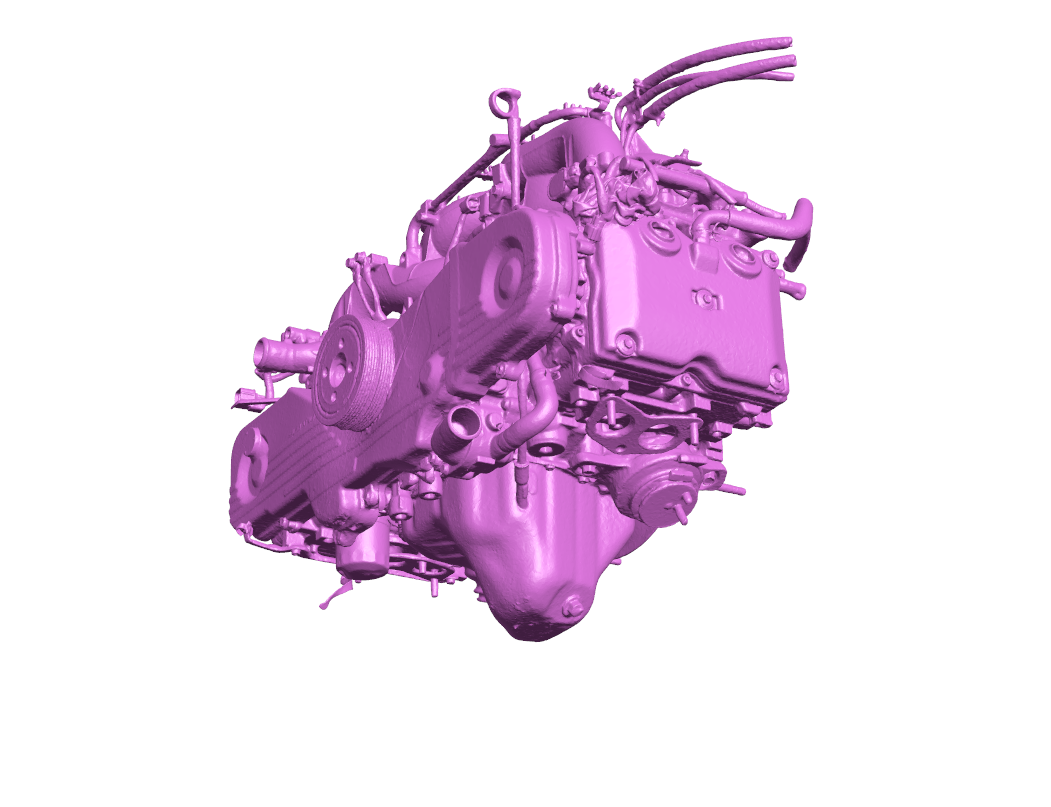
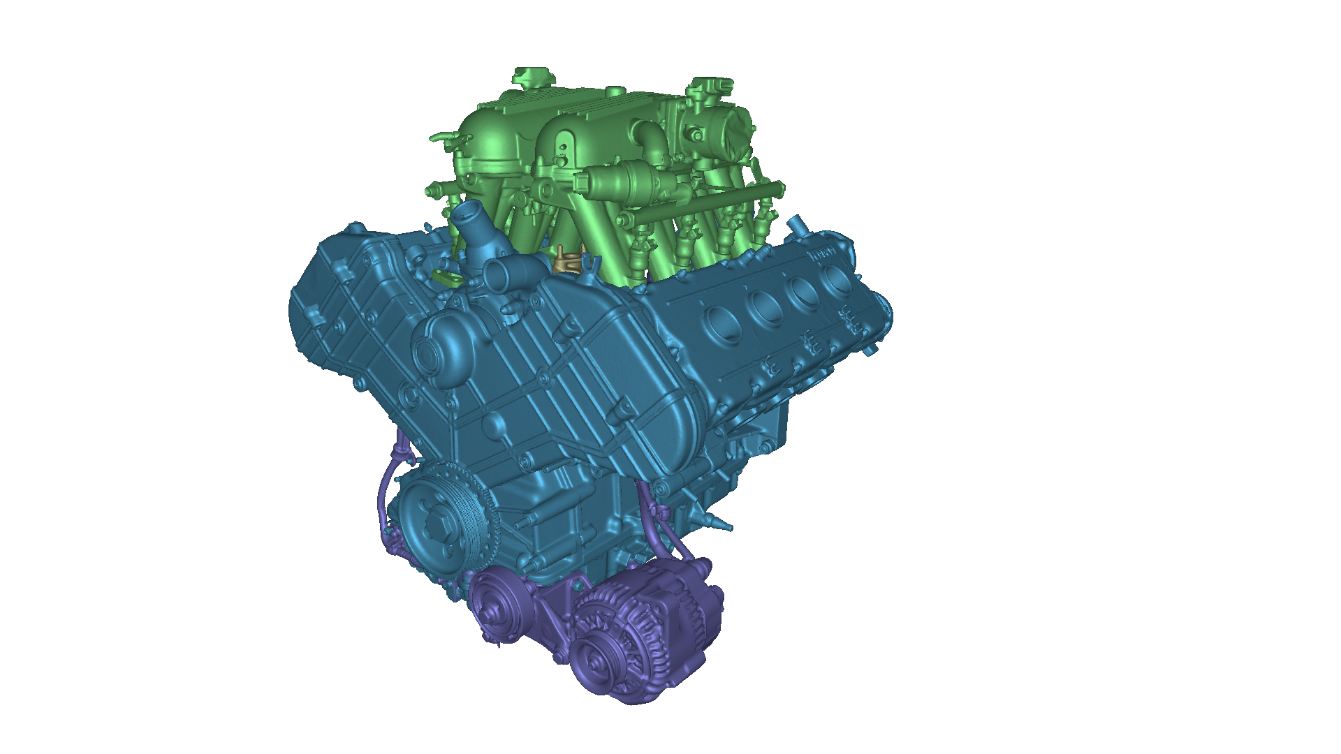
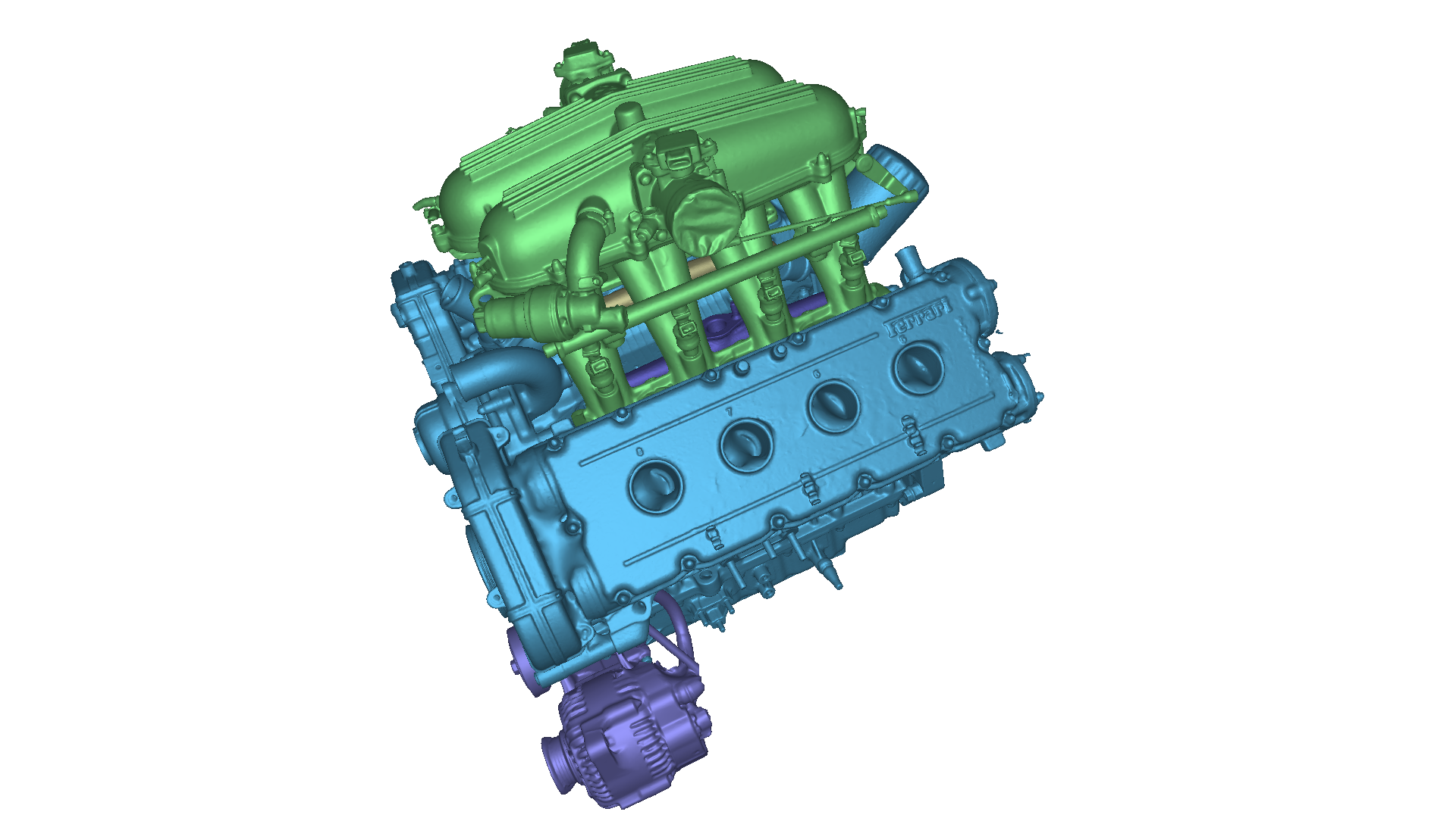
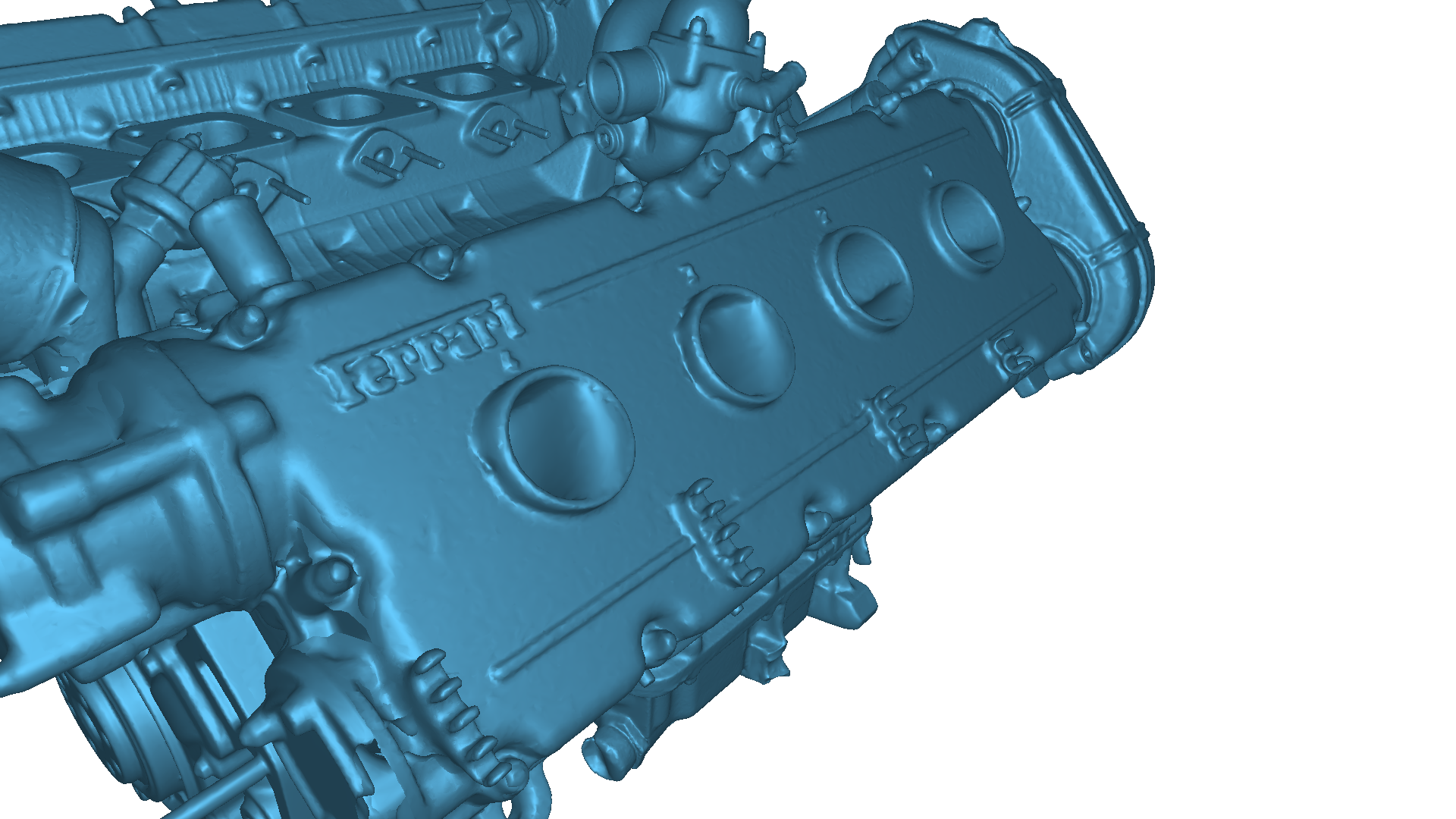
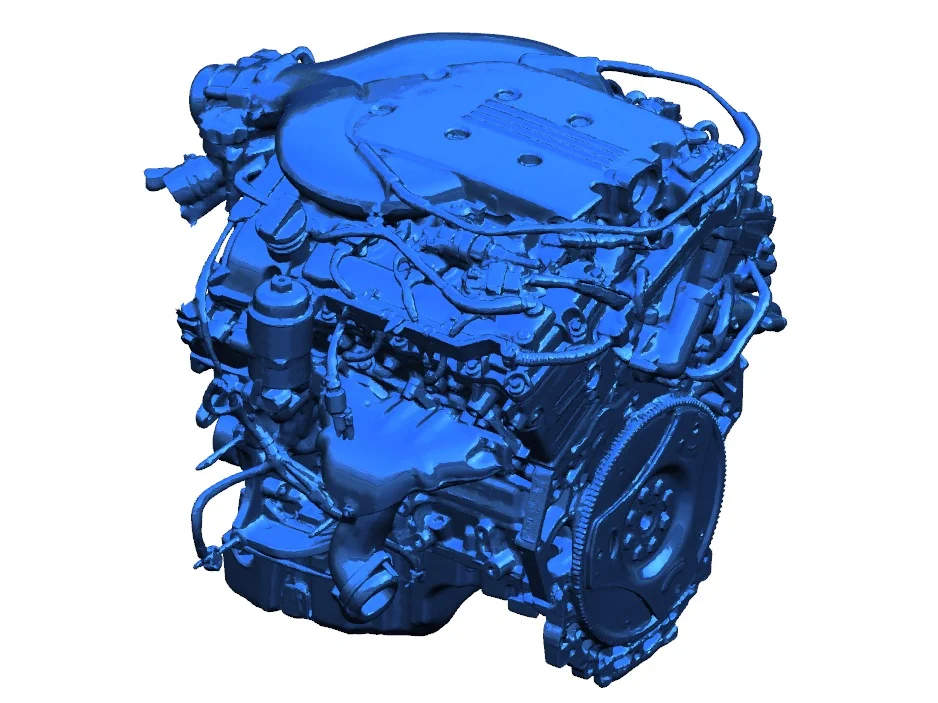
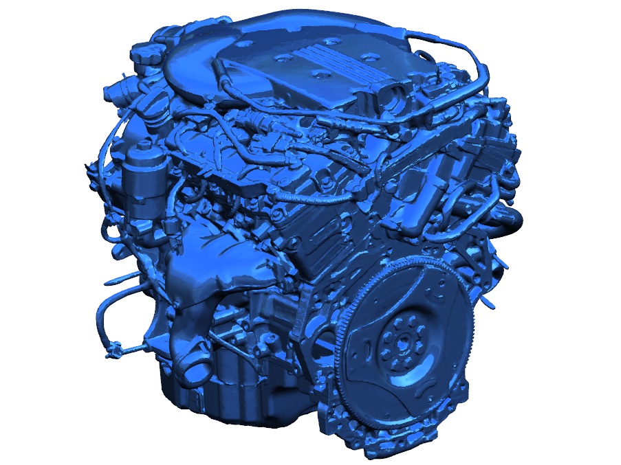
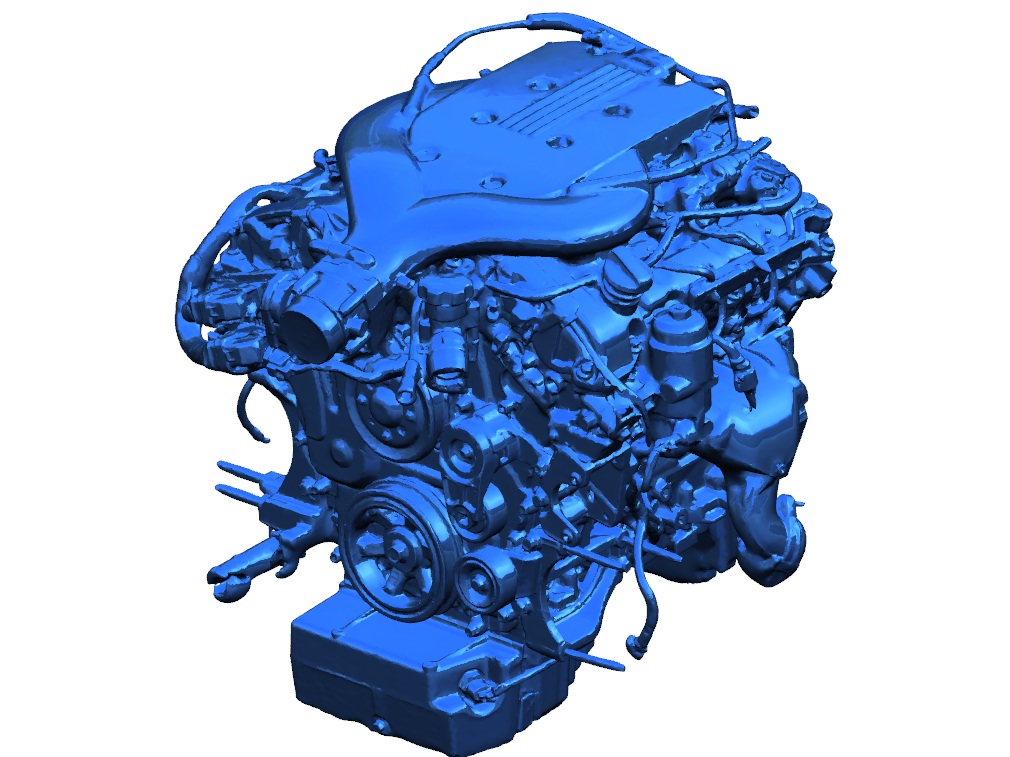
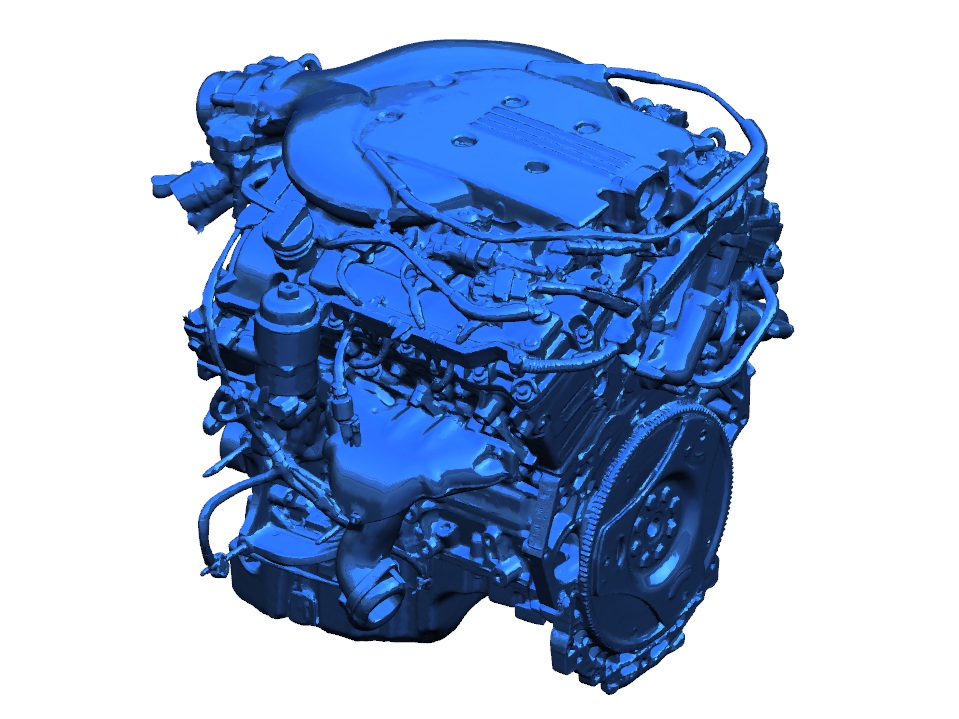
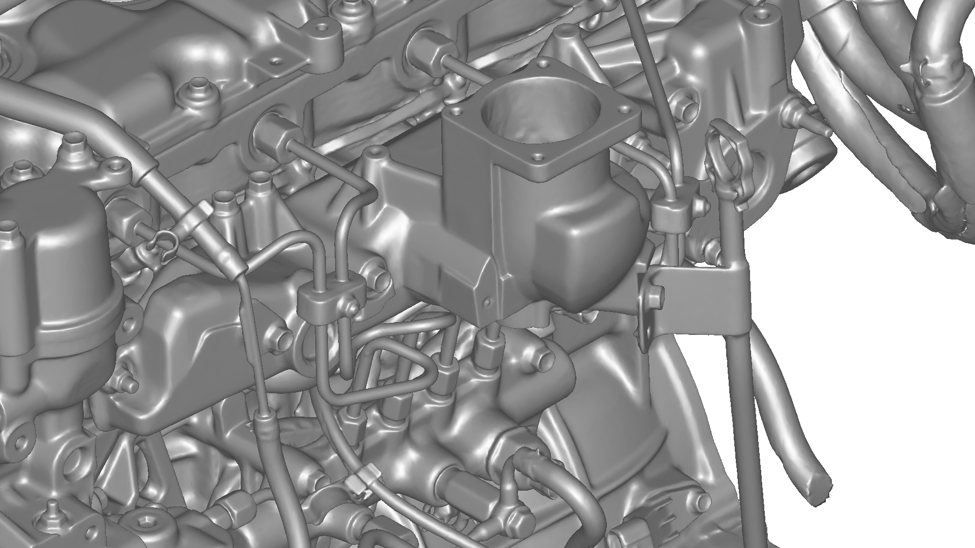
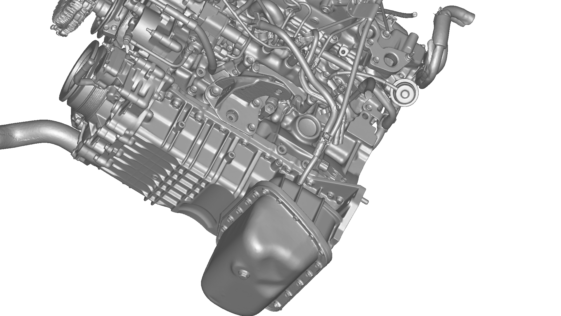
The scan contains the key external geometry required for most engineering and packaging applications; however, it is not a complete scan of every surface.
The block was mounted on an engine stand during scanning, resulting in reduced coverage and detail on the rear face of the block.
A crankshaft was installed during the scan. Internal geometry is therefore not fully represented.
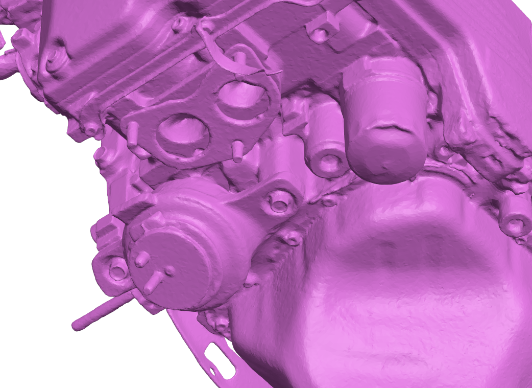
Small raised knobs visible on the scan are scan markers used during the capture process. These can be safely ignored or removed during post-processing if desired.
Scan is not watertight or fully complete; some areas may require cleanup or surface reconstruction depending on your intended workflow.
External geometry only; no complete internal engine geometry is included.
Collaborator Notes
Good quality scan of the important external geometry.
Rear face coverage is limited due to the engine being mounted on an engine stand during scanning.
The block contained a crankshaft during the scan.
Small protrusions visible on the scan are alignment markers that were intentionally placed in unobtrusive locations and do not represent part geometry.
Disclaimer
We encourage you to download the sample file to assess scan format, output quality, and compatibility with your preferred software before purchase. Different CAD and mesh-processing packages may interpret scan data differently, so verifying compatibility with your workflow is recommended.
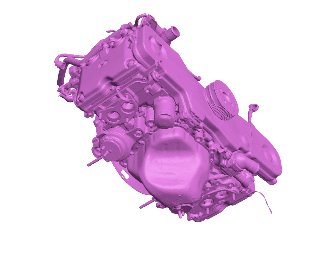
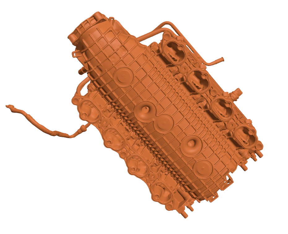
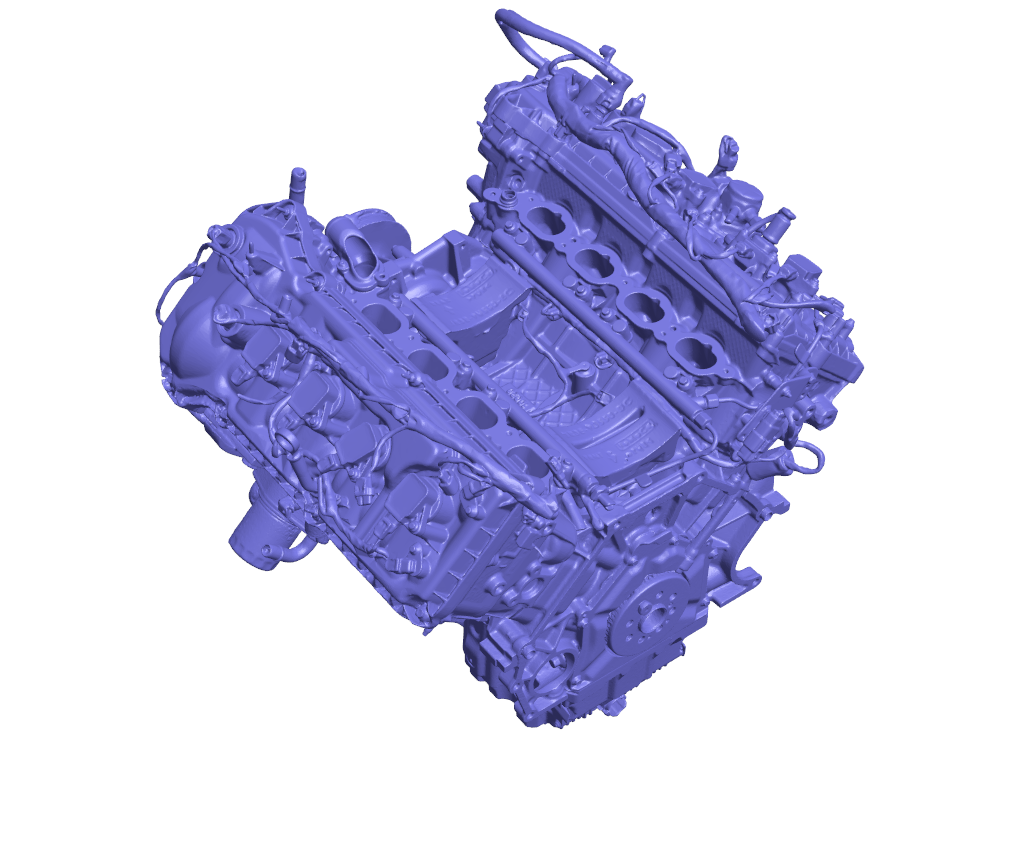
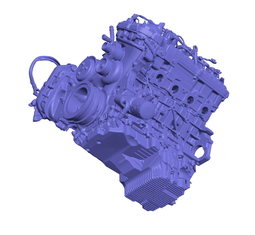
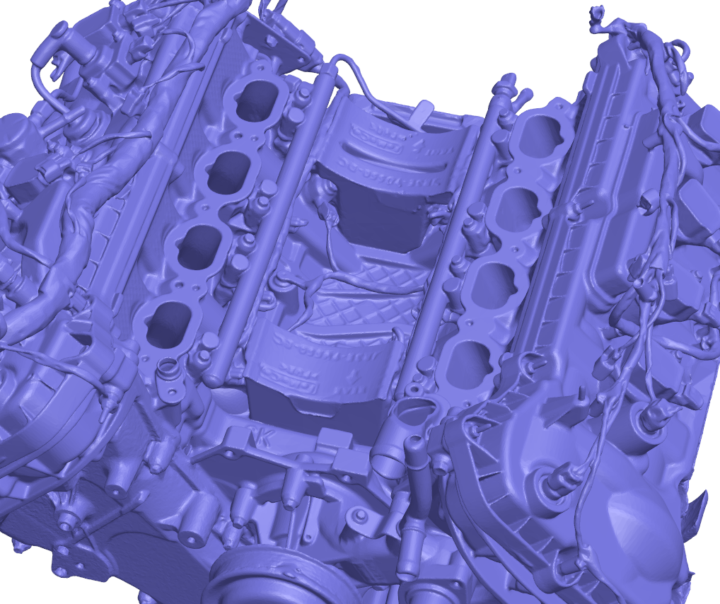
Please refer to the provided part images to evaluate scan quality, coverage, and overall representation.
While every effort is made during scanning to ensure accuracy, we recommend verifying critical dimensions against the physical component if your application requires tight tolerances or manufacturing-level precision.
Reviewing both the sample file and reference images will help ensure the scan meets your requirements prior to purchase.
Collaborator: Matthew Hillocks
This listing provides a high-resolution 3D scan of a Ford Windsor 351 engine block, capturing the key external casting geometry and major mounting interfaces used across a wide range of Ford V8 applications. The scan is well suited for engine development, fitment validation, reverse engineering, and CAD-based engineering workflows.
The Ford Windsor 351 (351W) is a cast iron 90-degree V8 engine block that has become one of Ford's most popular small-block platforms. Its widespread use in passenger cars, trucks, motorsport, and aftermarket performance applications makes it a valuable reference for restoration, fabrication, and custom engine projects.
Scan Compatibility
Compatible with Ford Windsor 351 engine applications (please verify your specific block variant and configuration for your intended use).
Common Applications
Engine bay layout and packaging
Engine mount and accessory bracket development
Custom fabrication and engine swap projects
Reverse engineering for replacement or performance parts
CAD reference and engineering workflows
3D visualization and simulation
File Suitability
Ideal for CAD reference, packaging studies, reverse engineering, and vehicle engineering workflows.
Important Notes
The scan contains the key external geometry required for most engineering and packaging applications; however, it is not a complete scan of every surface.
The block was mounted on an engine stand during scanning, resulting in reduced coverage and detail on the rear face of the block.
A crankshaft was installed during the scan. Internal geometry is therefore not fully represented.
Small raised knobs visible on the scan are scan markers used during the capture process. These can be safely ignored or removed during post-processing if desired.
Scan is not watertight or fully complete; some areas may require cleanup or surface reconstruction depending on your intended workflow.
External geometry only; no complete internal engine geometry is included.
Collaborator Notes
Good quality scan of the important external geometry.
Rear face coverage is limited due to the engine being mounted on an engine stand during scanning.
The block contained a crankshaft during the scan.
Small protrusions visible on the scan are alignment markers that were intentionally placed in unobtrusive locations and do not represent part geometry.
Disclaimer
We encourage you to download the sample file to assess scan format, output quality, and compatibility with your preferred software before purchase. Different CAD and mesh-processing packages may interpret scan data differently, so verifying compatibility with your workflow is recommended.
Please refer to the provided part images to evaluate scan quality, coverage, and overall representation.
While every effort is made during scanning to ensure accuracy, we recommend verifying critical dimensions against the physical component if your application requires tight tolerances or manufacturing-level precision.
Reviewing both the sample file and reference images will help ensure the scan meets your requirements prior to purchase.

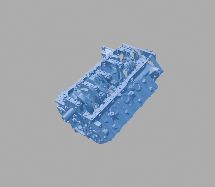 Image 1 of 6
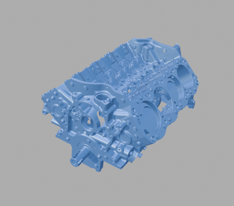 Image 2 of 6
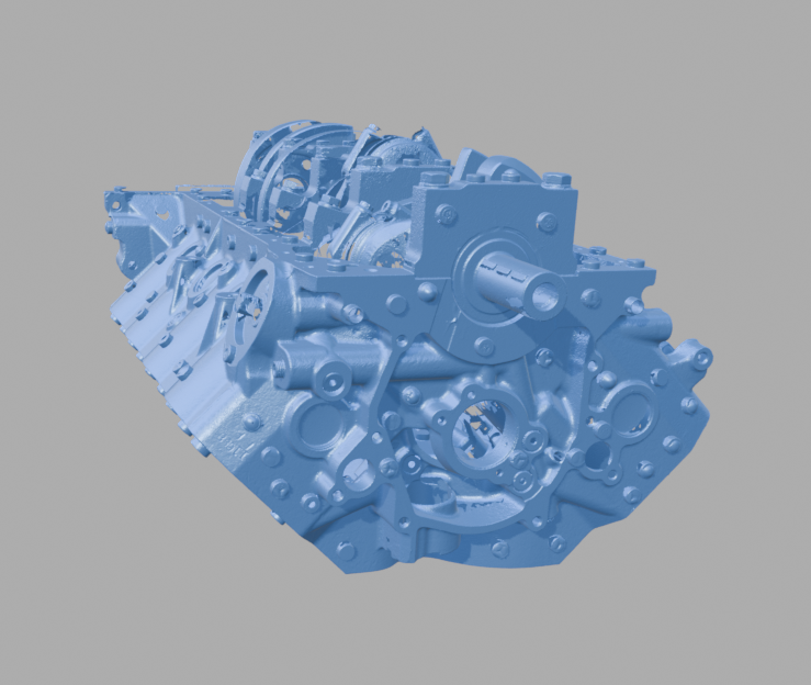 Image 3 of 6
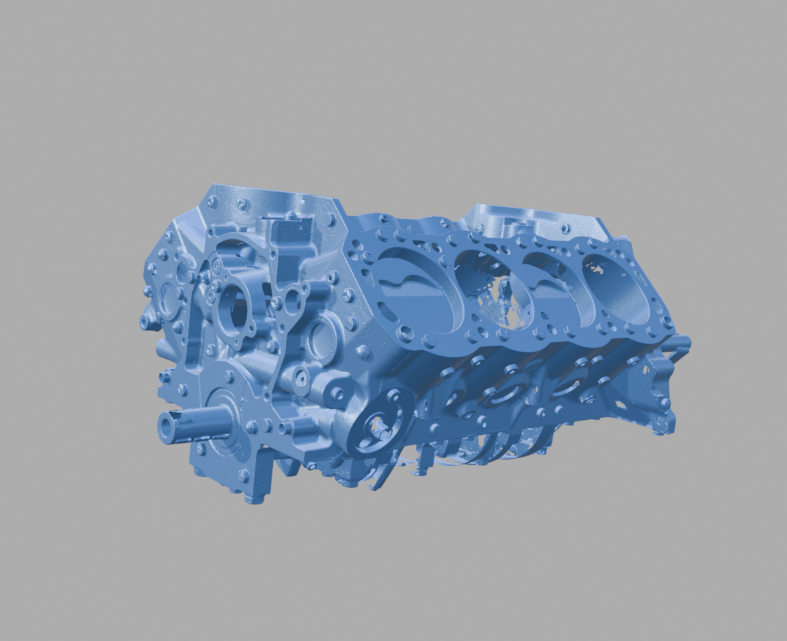 Image 4 of 6
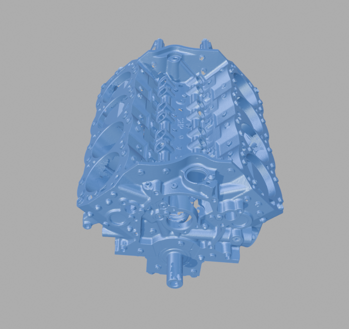 Image 5 of 6
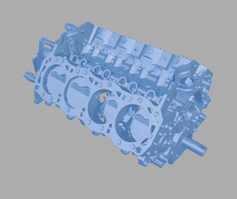 Image 6 of 6




![Subaru EJ25 Engine - 3D Scan (STL) [Item: SBU]](https://images.squarespace-cdn.com/content/v1/5aaee99b96e76f27dc94b28a/412e7960-c3f3-4c56-9872-56e2e81ff340/EJ25+%28AU+FORESTER%29+1.png)